
Setting inter-VLAN communication in Netgear ProSafe switches

Recently, I was trying to configure VLANs in order to create more logical network view and increase the security of the network by limiting the traffic from the different types of machines through the router ACLs. In order to do that, I had two level-3 switches: Netgear ProSafe GS728TS and Netgear ProSafe GS516TP.
With my basic understanding of VLANs, I thought it would be simple to do the change, but unfortunately, the web-based administration panel of the switches made it much more cryptic and complex compared to what can be done with Cisco IOS.
This article describes the final, step by step procedure to follow to setup VLANs on the switch. The idea is to be able to have separate VLANs where:
- Any device can communicate with devices from other VLANs, unless prevented by switches' ACLs.
- A device from one VLAN cannot eavesdrop on communications between devices from other VLANs.
This is, essentially, the most current need for small businesses and software developers. One of the goals, for instance, is to keep the production servers apart from, say, Wi-Fi devices, while allowing both the servers and the Wi-Fi devices to communicate with each other and to access the Internet.
Setting up VLANs
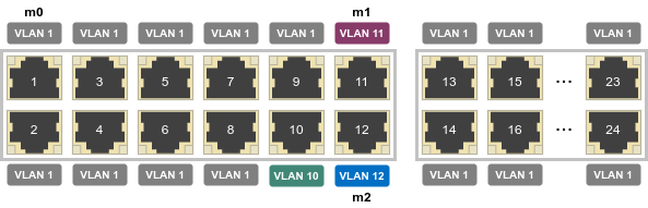
In lab, use GS516TP and three Linux machines named m0, m1, and m2, connected like this:
Here's the initial configuration of m0, that doesn't use the VLANs yet (since they are not yet configured):
auto eth0
iface eth0 inet static
address 192.168.0.2
gateway 192.168.0.239
netmask 255.255.0.0
Factory-reset the switch, then go to 192.168.0.239 (the default IP of the switch) from m0.
Go to Security › Access › HTTP Configuration. Set HTTP session soft timeout to 60 minutes.
Go to Routing › VLAN › VLAN Routing Wizard and create three VLANs:
- VLAN ID 10, IP address 192.168.10.1, network mask: 255.255.255.0, port 10 untagged.
- VLAN ID 11, IP address 192.168.11.1, network mask: 255.255.255.0, port 11 untagged.
- VLAN ID 12, IP address 192.168.12.1, network mask: 255.255.255.0, port 12 untagged.
Configure m1 to use VLAN 11, like this:
auto eth0
iface eth0 inet static
address 192.168.11.2
gateway 192.168.11.1
netmask 255.255.0.0
Similarly, m2 would look like this:
auto eth0
iface eth0 inet static
address 192.168.12.2
gateway 192.168.12.1
netmask 255.255.0.0
Reboot m1 and m2, and access the configuration page of the switch from m1 at 192.168.11.1.
Unplug m0 from port g1 and connect it to the port g10:
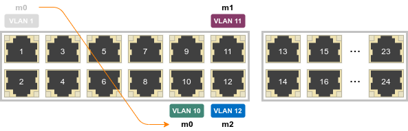
The machine shouldn't be able to connect, since the port is configured as VLAN 10, and the IP address of the machine is invalid for this VLAN. Reconfigure m0 like this:
auto eth0
iface eth0 inet static
address 192.168.10.2
gateway 192.168.10.1
netmask 255.255.0.0
Reboot m1. This time, it should be able to connect. A ping from one machine to another should work, but shouldn't be traceable from a third machine. For instance, m0 $ ping 192.168.11.2 should work, but a Wireshark dump running from m2 shouldn't show any of the packets.
The switch is properly routing the packets from one VLAN to another. However, it has no idea what to do with the packets targeting the machines outside the local network. In other words, even if one of the three machines was an actual router with Internet access, the two other machines wouldn't be able to access the Internet.
Important note: if the ping doesn't work as expected, do ip route show, and then ip route delete 192.168.../... the invalid records.
Accessing Internet
One of my mistakes was to think that the configuration in System › Management › IP Configuration was important, especially the default gateway. It's not, and it seems like the value shouldn't be changed.
Instead, go to Routing › Routing Table. Add DefaultRoute with next hop IP address 192.168.11.2, preference 1.
Now, when doing ping 192.168.12.2 from m0, the ping will still work the same as before, and m1 will not see the packets. On the other hand, when doing ping 1.2.3.4, it will be seen by Wireshark on m1 (and the ping will fail, because the "gateway" doesn't know what to do with the packet).
DHCP configuration
Having machines which talk to each other is great, but it's even greater when one doesn't have to manually configure the gateway and other stuff. I'm using ISC DHCP, and when reconfiguring it by adding several subnets, I discovered that it starts ignoring the host directives.
In fact, DHCP server was on an untagged port of the switch, and so it was using a single interface eth0. On the other hand, multiple subnet configuration like the one used in most examples on the Internet expects the DHCP server to have multiple interfaces, would it be an eth0 on first LAN and eth1 on the second one, or an eth0.10, eth0.11, etc. in a case of multiple VLANs with a trunked port.
The solution was to enclose all subnets in a shared-network block. The documentation is perfectly clear about that when you look for the directive, but when you don't know that the directive exists in the first place, discovering it may not be that easy.
Here's an example of the configuration file:
shared-network everything {
    # VLAN 10.
    subnet 192.168.10.0 netmask 255.255.255.0 {
        option subnet-mask 255.255.0.0;
        option broadcast-address 192.168.10.255;
        option routers 192.168.10.1;

        pool {
            failover peer "dhcp-backbone";
            max-lease-time 1800;
            range 192.168.10.200 192.168.10.254;
        }
    }

    # VLAN 11.
    subnet 192.168.11.0 netmask 255.255.255.0 {
        option subnet-mask 255.255.0.0;
        option broadcast-address 192.168.11.255;
        option routers 192.168.11.2;  # The router itself.

        pool {
            failover peer "dhcp-backbone";
            max-lease-time 1800;
            range 192.168.11.200 192.168.11.254;
        }
    }

    # VLAN 12.
    subnet 192.168.12.0 netmask 255.255.255.0 {
        option subnet-mask 255.255.0.0;
        option broadcast-address 192.168.12.255;
        option routers 192.168.12.1;

        pool {
            failover peer "dhcp-backbone";
            max-lease-time 1800;
            range 192.168.12.200 192.168.12.254;
        }
    }

    host m0 {
        hardware ethernet 12:34:56:78:90:AB;
        fixed-address 192.168.10.2;
    }

    host m1 {
        hardware ethernet CD:EF:12:34:56:78;
        fixed-address 192.168.11.2;
    }

    host m2 {
        hardware ethernet 90:AB:CD:EF:12:34;
        fixed-address 192.168.12.2;
    }
}
Here's the list of resources which helped me to figure out the things described above:
- What is VLAN Routing?
- How to configure routing VLANs on a NETGEAR managed switch with shared internet access
- How do I configure VLAN Routing on a smart switch?
- How to prevent packets from being seen from devices which belong to other VLANs?
- How to make the devices belonging to two separate VLANs to communicate together?
- Why am I seeing unicast packets from a machine on another VLAN?
- Why is ISC DHCP server ignoring the fixed-address statement?
- GS108Ev3 Multi Port Based VLAN technical details